摘要:
锂资源需求激增使得盐湖卤水提锂成为研究热点。相较于传统提锂技术,电容去离子技术因能耗低、污染小、回收效率高、产品纯度高等优势受到广泛关注。本综述系统总结了CDI在卤水提锂中的研究进展,涵盖机理与装置设计,重点分析了四种提锂材料的晶体结构与提锂机制,深入探讨了材料改性手段的核心原理,详细列出了性能评价指标与材料对比,并对电极材料改性措施与未来发展方向提出了前瞻性展望。
1、全文速览
本文综述了CDI技术在盐湖卤水提锂领域的最新进展,从装置构型、材料结构、改性策略到性能评估进行全面剖析,为高性能锂提取电极的设计与应用提供理论指导。
2、背景介绍
锂离子电池(LIBs)因其高能量密度和功率密度的独特组合,已成为便携式电子产品和电动汽车的首选储能技术。市场应用的爆发式增长推动锂资源开发进入狂热阶段,自2013年以来,全球锂市场以15-20%的年复合增长率持续扩张。因此,拓展锂资源获取渠道具有重要的战略和商业价值。目前,全球锂资源主要赋存于两大类载体中:一是富锂卤水(以溶解态Li⁺形式存在),二是硬岩矿石(如锂辉石、锂云母等矿物)。据统计,全球碳酸锂和氯化锂产量的最大份额源自盐湖卤水。中国锂资源总量约占全球的22%,金属锂当量约300万吨,其中卤水锂资源占比高达约80%,主要分布在青海、西藏等高海拔地区。然而,盐湖卤水成分极为复杂,除锂外还富含钠、镁等阳离子以及氯离子、硫酸根、碳酸根等阴离子,导致锂浓度普遍偏低。开发高效、低耗、选择性强的CDI提锂技术,对于缓解锂资源短缺、推动新能源产业可持续发展具有重大意义。在锂提取应用中,CDI(通常基于离子嵌入原理)采用可选择性嵌入Li⁺的阴极材料,通过电压反转实现锂的脱嵌回收。这类材料已广泛应用于锂离子电池,其工作原理是Li⁺在电场作用下进入材料内部晶格通道,在特定位点迁移并嵌入过渡金属氧化物骨架,伴随金属价态变化产生反向电压。
3、图文解析
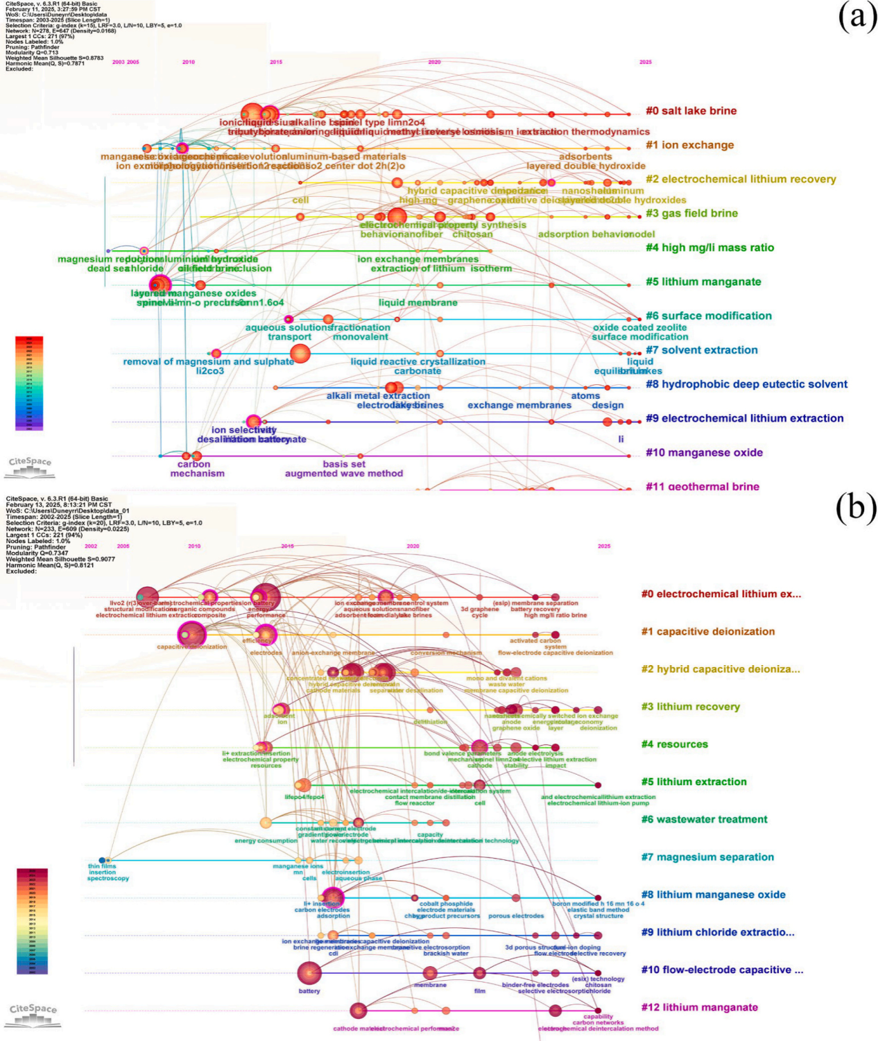
Figure1. (a) Research hotspots timeline (2002-2025) of lithium extraction from salt lakes searching in Web of Science Core Collection with keywords “brine” and “lithium extraction”, and (b) electrochemical lithium extraction searching with keywords “electrochemical” and “lithium extraction”
图1通过CiteSpace分析了2002-2025年盐湖提锂与电化学提锂的研究热点时序图,显示CDI、HCDI、FCDI为主要技术方向,锰基材料(如LiMn2O4)与磷酸铁锂(LiFePO4)为研究重点。
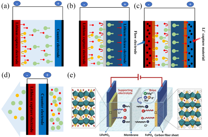
Figure2.Model drawings of different types of electrochemical lithium extraction devices (a) Single-chamber “flow-by” model; (b) battery-like model; (c) flowing electrode model; (d) “flow-through” model.
 : Li+;
 : other cations in solution;
 : anions in solution;
 : lithium selective adsorption material;
 :cation exchange membrane;
 :anion exchange membrane;
 :electrode spacer;
 :collector;
 : brine;
 : lithium-enriched solution; (f) Schematic diagram of lithium extraction from CDI model of class battery (taking lithium iron phosphate as an example).
图2展示了四种CDI提锂装置模型:(a)单流道式、(b)类电池式(含阴离子交换膜)、(c)流动电极式、(d)流通式,以及(e)以LiFePO4为例的电池式CDI提锂机理示意图,体现Li+在电场驱动下的嵌入/脱嵌过程。
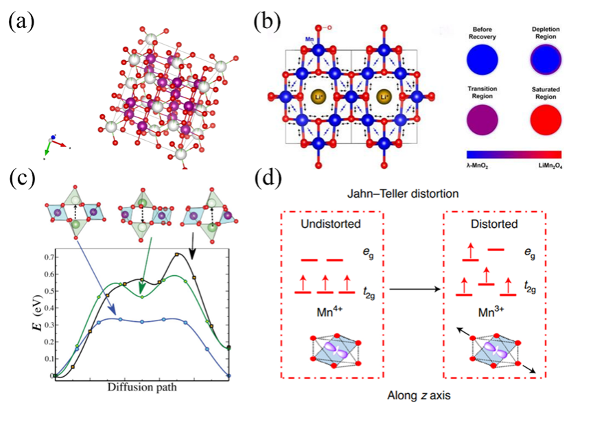
Figure3. (a) cell structure of spinel Li0.05Mn1.95O4(red: O, white: Li, purple: Mn), there is only 0.05 probability that lithium atoms will be present in the white sphere. (b) Changes in the length of Mn-O bonds in different regions during lithium insertion. (c) Energy barrier profiles of different diffusion paths in different sized crystallite. (d) the energy state split of valence electron orbital of manganese, and JT distortion.
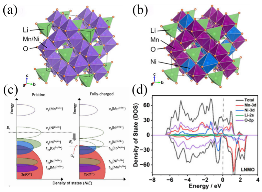
Figure4. The crystal structure of LNMO (a) disordered state, (b) ordered state. (c) Schematic representation of electronic configurations for Ni, Co, and Mn ions. The left panel depicts the ground state (uncharged), while the right panel illustrates the fully oxidized state. Electron occupancy is visualized through color-filled ellipses. (d) Density state of LNMO.
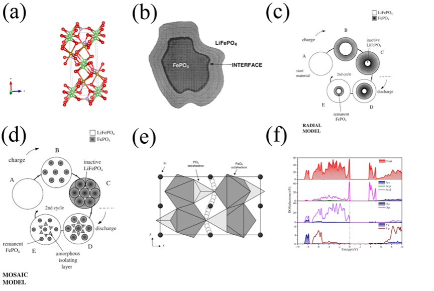
Figure5. (a)cell structure of olivine LiFePO4(red: O; brown: Fe; pink: P). Lithium iron phosphate phase transition model: (b)phase interface model, (c)core-shell model, (d)Mosaic model, (e)One-dimensional diffusion model, (f)Eigensystem state density of LFPO.
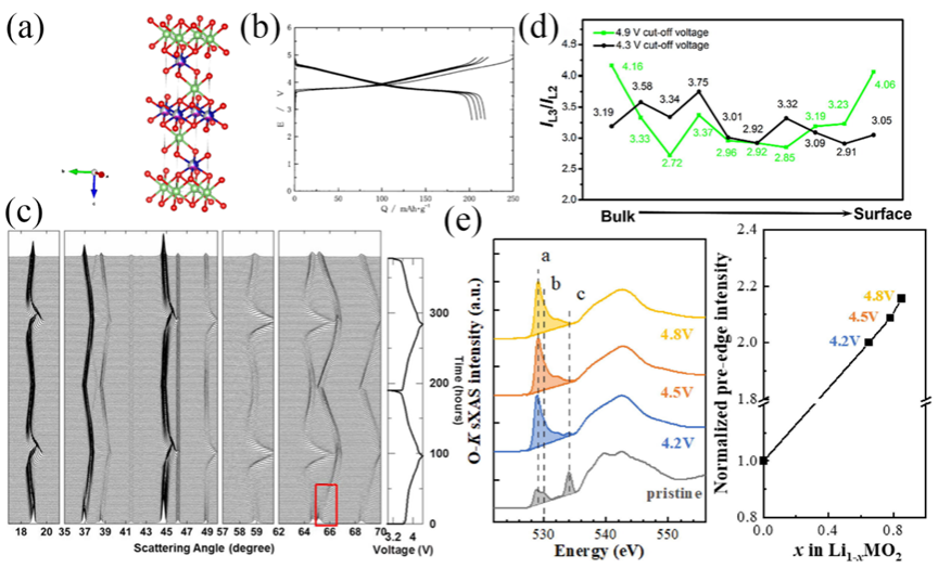
Figure6. (a)Crystal structure of NCM. (b)Charge and discharge curve of NCM. (c) Charge-discharge curves of NCM at 0.01C and in situ XRD. (d)The ratio of the L2 and L3 intensities of the L-edge electrons of Ni atoms as a function of atomic position. (e)K-edge sXAS spectra of O and the normalized intensity in pre-edge region.
图3-6通过晶体结构图、能带图、充放电曲线等揭示了材料在锂嵌入过程中的相变、电子结构变化与性能关联。材料结构分析:LiMn2O4(LMO):尖晶石结构,Li+占据8a四面体位点,Mn存在Jahn-Teller效应导致结构畸变,影响循环稳定性。LiNi0.5Mn1.5O2(LNMO):Ni掺杂提升电压平台,但水相中Ni2+/Ni4+平台无法利用,容量受限。LiFePO4(LFPO):橄榄石结构,Li+沿b轴一维扩散,导电性差,充放电过程存在相界面、核壳等多相转变模型。Li1-xNi1/3Co1/3Mn1/3O2(NCM):层状结构,Ni/Co贡献容量,Mn4+稳定结构,但循环中晶格膨胀导致颗粒裂纹。
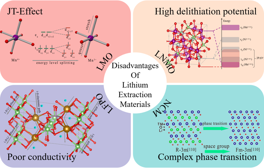
Figure 7. Disadvantages of lithium extraction materials (Schematic diagrams of the NCM have been copyrighted for use at ELSEVIER).
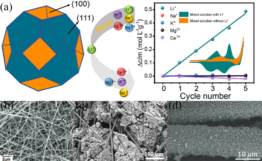
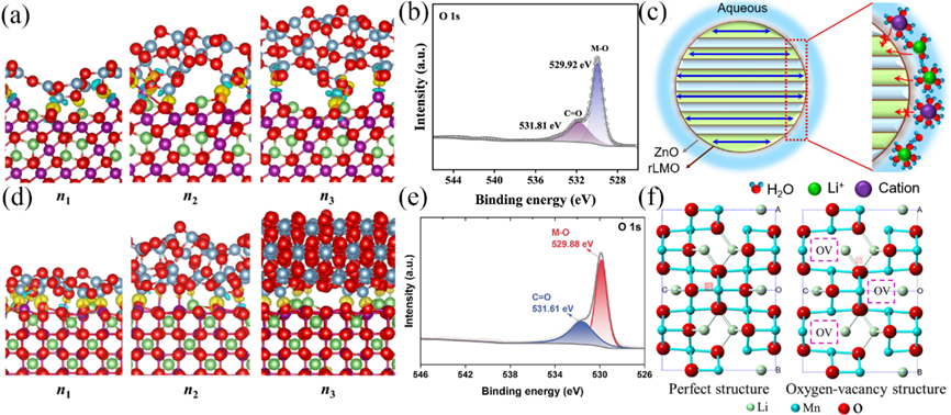
Figure 8. Differences in the interfacial structure and charge density of alumina-coated LMOs with different numbers of layers (n1, n2, n3) for {1132} configuration (a) and {3121} configuration (d), blue area indicates charge deficiency, yellow area indicates charge accumulation, purple ball indicates Mn, green indicates Li, light blue indicates Al . XPS analysis of the O1s orbitals of pure LMO (b), LMO after In2O3modified (e).(c) Dehydration of hydrated cations on ZnO-LMO surfaces and selective embedding in materials. (f) perfect structure and Oxygen-vacancy structure of LMO.
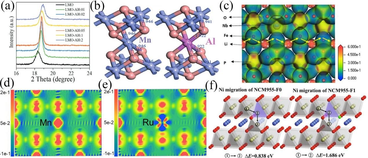
Figure 9. (a) Doping with Al atoms causes the XRD peak shift of LMO, (b) The site of Al atoms in the lattice after doping, (c) The electron localization function map of Nb-doped LFPO, the amount of electron localization around Nb atoms is smaller than that around Fe atoms, and the diffusion energy barrier is reduced. Charge density of LMO (d) and Ru dopped LMO (e). (f) Schematic diagram of Ni diffusion pathways in NCM955-F0 and NMC955-F1.
Figure 10. (a) The orientation of the chamfered octahedral LMO crystal surface and its selective lithium extraction performance. (b) SEM images of the synthesized single crystalline spinel LiMn2O4nanowires. (c) Morphology of PEG-modified porous LiFePO4electrode. (d) SEM images of LiMn2O4nanosheets.

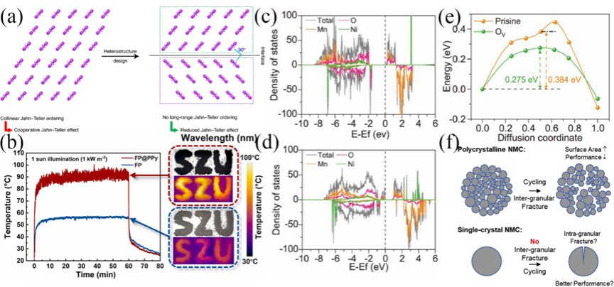
Figure 11. (a) Failure of the JT effect due to clamped orbitals. (b) Temperature changes of FP and FP@PPy under 1 sun simulation light. The inset on the right shows digital images and infrared thermal images. The density of states of LNMO-Pristine (c) and LNMO-OVs (d); (e) Comparison of lithium diffusion energy barrier curves for LNMO-Pristine and LNMO-OVs. (f) Different reactions at grain boundaries during cycling of polycrystalline and monocrystalline NCM.
图8-11展示了改性后材料的结构优化与性能提升机制。
表面改性:Al2O3包覆:形成致密保护层,抑制Mn溶解,电荷重新分布降低锂空位形成能;碳材料复合:提高电子电导率,构建三维导电网络;ZnO修饰:增强表面亲水性,促进离子界面传输。
元素掺杂:阳离子掺杂(Al、Ru、Nb等):稳定晶体结构,抑制Jahn-Teller效应;调节能带结构,提高电导率;扩大离子扩散通道;阴离子掺杂(F等):增强金属-配体键合强度;抑制过渡金属迁移;提高结构稳定性。
形貌调控:纳米结构设计:增大比表面积,缩短离子扩散路径;晶体面工程:控制(100)和(111)晶面暴露比例,平衡扩散速率与稳定性;多级孔结构:优化质量传输和离子可达性。
其他调控:异质结构与缺陷调控策略。
4、总结与展望
尽管CDI技术在选择性提取锂方面展现了潜力,但目前仍面临电极材料不稳定、锂嵌入速率低和能耗高等关键挑战。未来的研究重点应围绕三方面展开:一是开发新的材料改性策略,如利用多元掺杂或冠醚等有机涂层来提升选择性和稳定性;二是攻克工程瓶颈,实现连续、高效的低能耗运行,例如探索流动电极技术的实际应用;三是将CDI与沉淀、纳滤、电渗析等传统技术集成,构建多级处理系统,并通过优化操作参数来全面提高提锂效率并降低成本。
文献链接:
https://doi.org/10.1016/j.ccr.2025.217339
